Frequency Control with Quartz Crystals
| Engineering Bulletin E-6: Frequency Control with Quartz Crystals |
Crystal oscillators, operating at all but very low frequencies, can be directly keyed for radiotelegraphy. Keying is accomplished in a variety of manners, although interruption of the cathode circuit is most common. Other methods include breaking the primary circuit of the oscillator power supply, opening the screen-grid circuit with pentode or tetrode tubes, applying high negative bias to the suppressor grid of pentodes, control-grid blocking, and shorting or opening the crystal circuit.
To prevent "chirping" when keying to the oscillator, the screen-grid potential for tetrode or pentode tubes should be obtained by means of a voltage divider rather than a series dropping resistor. This prevents the existence of high screen-grid voltage at the instant the key is depressed. When keying in the cathode circuit, best results are obtained when the cathode of both the oscillator and the first buffer are simultaneously interrupted. The two cathode leads can be tied together beyond their individual biasing resistors and r.f. bypass condensers such that the key can be connected between the common lead and ground. A key click filter is ordinarily necessary whether one or both cathode circuits are keyed but, usually, the use of a condenser and resistor in series across the key terminals is sufficient (C, 1/4 to 2 mfd.; R, 200 to 20,000 ohms). If further filtering is necessary, a choke with an inductance of from 1 to 5 henries can be connected in series with the keying circuit. The choke should, of course, be relieved of r.f.
An effective but not commonly employed keying system consists of directly shorting the crystal or of opening one crystal connection. Either arrangement naturally requires the use of a keying relay located close to the crystal such that very short connecting leads can be realized. When the crystal is to be shorted, a good quality mica condenser with a capacity of .002 mf. or greater should be connected in series with the crystal circuit to prevent disturbance of normal bias conditions in the oscillator.
Keying can also be effected by control-grid blocking; that is, through the application of a high negative voltage to the control grid when the key is open. Unless the keying bids is high and can be applied instantly, however, clean characters may not result. This is caused by the fact that an increase of bias generally will be accompanied by higher crystal excitation and some increase in output. If the bias change is not instantaneous, the output may increase momentarily before dropping to zero upon opening of the keying contacts. In addition, if the time of full application is sufficiently slow (caused by delay in resistance-capacity combinations), the crystal might be fractured as a result of operation under a high bias condition. Suppressor-grid blocking has less influence on crystal performance but, in the Tri-tet and similar circuits, the crystal will continue to oscillate when the key is open. This may or may not be undesirable, depending upon individual operating conditions.
Low frequency crystal oscillators (below 200kc.) cannot be satisfactorily keyed at reasonable speeds because of the relatively slow rate at which the crystal goes into oscillation. Also, at very high frequencies, it often is difficult to obtain a signal entirely free from chirping. Either of these difficulties can be eliminated in a multistage transmitter by keying one or more of the intermediate stages and allowing the crystal oscillator to run continuously. Under such conditions, the ability of the crystal to follow keying has no bearing on transmitter performance. Furthermore, if a buffer stage exists between the oscillator and the keyed stages, small changes in operating frequency (chirping) caused by varying oscillator loading under keying are eliminated. In this respect, it should be noted that oscillator circuits such as the Tri-tet (figure 15) and the Pierce oscillator-multiplier (figure 11) possess some buffering action by virtue of the electronic coupling existing between the oscillator proper and the output circuit.
An objection to keying stages other than the oscillator lies in the fact that a local radiation may exist from the continuously running portion of the transmitter. This is undesirable for break-in operation or for local monitoring and can be eliminated only by thorough shielding of the radiating stages or by remote control of the transmitter. Also, unless the transmitter is carefully designed and adjusted, a back wave may be transmitted.
Figure 17 illustrates a method whereby the desirable features of direct oscillator keying and of inter-stage keying can be combined. This system, like simple inter-stage keying, is excellent for high speed telegraphy even with sluggish crystals. An added feature, however, is that the oscillator is 'dead' during the time the key is open.
Referring to the diagram, it will be seen that, when the key is open, the cathode circuit of the keyed inter-stage is incomplete and the crystal oscillator is inoperative because the crystal circuit is shorted to ground. Upon depressing the key, the oscillator is permitted to function but a signal is not transmitted until the relay contacts complete the cathode circuit of the additionally keyed stage. The time interval introduced by the relay allows the crystal oscillation to approach full operating value before a signal is radiated by the transmitter. This time delay reduces the possibility of a ragged signal due to slow crystal starting, or chirping due to changing oscillator loading. As in simple inter-stage keying, it is desirable, of course, to have at least one buffer stage between the oscillator and the keyed amplifier.
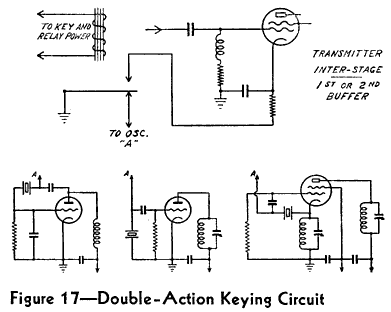
The time delay is adjustable by the relay contact spacing and should be set at the minimum value consistent with clean characters. Naturally, the relay should be well designed such that bouncing of the contacts will not occur. If oscillator control is obtained by crystal shorting as shown in the diagram, the leads to the relay contacts, particularly from the oscillator, must be very short. Under proper conditions of adjustment and operation, the transmitted characters can be made to approach a square wave in characteristics without the presence of disturbing keying transients which would otherwise normally occur.
It is not necessary, incidentally, to key the oscillator by crystal shorting as shown. By the use of appropriate relay contacts or multiple relays, the oscillator can be keyed by any other desirable method. The primary consideration is to introduce a time interval between the starting of the oscillator and the actual transmission of a signal.
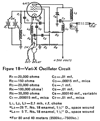
The oscillator arrangement in the Bliley Vari-X (Footnote 8) is an example of circuit design for clean keying characteristics and very low crystal excitation with reasonable power output. Figure 18 shows the wiring diagram of the oscillator and indicates correct values for 40-meter, and 80-meter crystals. Through the use of the high transconductance 6AC7 tube in conjunction with proportioned control-grid and screen-grid feedback, excellent keying ability is realized. At the same time, essentially constant power output occurs with variable frequency crystals over the adjustable frequency range and the power output at 40-meters is nearly the same whether a 40-meter crystal be used or an 80-meter crystal be employed for doubling to 40-meters.
In general, when a crystal oscillator is to be keyed, the oscillator should be considerably detuned from resonance and operated with a relatively light load. If the oscillator is loaded heavily and tuned for maximum output, chirping and skipping of characters can result.